67 Results
View results:
Sort by:

Creating a validation example for Computational Fluid Dynamics (CFD) is a critical step in ensuring the accuracy and reliability of simulation results. This process involves comparing the outcomes of CFD simulations with experimental or analytical data from real-world scenarios. The objective is to establish that the CFD model can faithfully replicate the physical phenomena it is intended to simulate. This guide outlines the essential steps in developing a validation example for CFD simulation, from selecting a suitable physical scenario to analyzing and comparing the results. By meticulously following these steps, engineers and researchers can enhance the credibility of their CFD models, paving the way for their effective application in diverse fields such as aerodynamics, aerospace, and environmental studies.

In this article, a heavy cargo box is calculated according to the guidelines of the German Bundesverband Holzpackmittel (HPE). The load cases for Handling by Crane and Sea Transport are calculated.

Line releases are special objects in RFEM 6 that allow structural decoupling of objects connected to a line. They are mostly used to decouple two surfaces that are not rigidly connected or transferring only compressive forces at the common boundary line. By defining a line release, a new line is generated at the same place which transfers only the locked degrees of freedom. This article will show the definition of line releases in a practical example.

Defining the appropriate effective length is crucial in obtaining the correct member design capacity. For X-bracing that is connected at the center, engineers often wonder if the full end-to-end length of the member shall be used, or whether using half of the length to where the members are connected is sufficient.This article outlines the recommendations given by the AISC and provides an example on how to specify the effective length of the X-braces in RFEM.

The new RFEM software generation provides the option to perform stability design of tapered timber members in line with the equivalent member method. According to this method, the design can be performed if the guidelines of DIN 1052, Section E8.4.2 for variable cross-sections are met. In various technical literature, this method is also adopted for Eurocode 5. This article demonstrates how to use the equivalent member method for a tapered roof girder.

This article describes how a flat slab of a residential building is modeled in RFEM 6 and designed according to Eurocode 2. The plate is 24 cm thick and is supported by 45/45/300 cm columns at distances of 6.75 m in both the X and Y directions (Image 1). The columns are modeled as elastic nodal supports by determining the spring stiffness based on the boundary conditions (Image 2). C35/45 concrete and B 500 S (A) reinforcing steel are selected as the materials for the design.

RFEM 6 includes the Form-Finding add-on to determine the equilibrium shapes of surface models subjected to tension and members subjected to axial forces. Activate this add-on in the model's Base Data and use it to find the geometric position in which the prestress of lightweight structures is in equilibrium with the existing boundary conditions.

In RFEM and RSTAB, there are various options to renumber the individual structural elements, such as nodes, lines, members, surfaces, or solids. Two options are available for renumbering: singly and automatically.
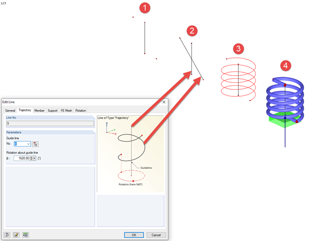
In RFEM, you can create screw lines using the "Trajectory" type line. To do this, you need a center line/guide line around which the line can be modeled, as well as a start and end point. Then, you can create a "Trajectory" type line between the start and end points; this initially appears as a straight line.

If you want to consider guide objects in the overall view (F8 key or double-click on the mouse wheel) or, for example, in a particular direction of the views, you can enable this option in the settings of the particular guide objects (guidelines, background layers, line grids).

A member's boundary conditions decisively influence the elastic critical moment for lateral-torsional buckling Mcr. The program uses a planar model with four degrees of freedom for its determination. The corresponding coefficients kz and kw can be defined individually for standard-compliant cross-sections. This allows you to describe the degrees of freedom available at both member ends due to the support conditions.
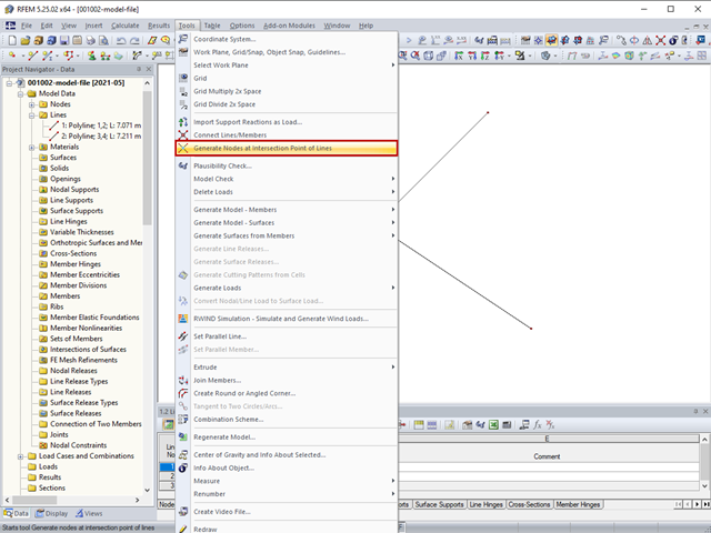
The "Generate Nodes at Intersection Points of Lines" option creates a node at the intersection points of lines without splitting the lines.

In RFEM, you can display the contact properties between two surfaces by means of contact solids.
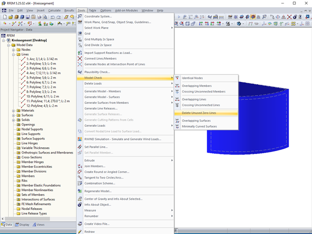
When creating or importing a model, it can happen that lines with a length of zero are created.
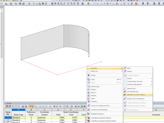
In RFEM, the function is implemented to generate a surface automatically from lines perpendicular to the work plane.

In the age of BIM, data exchange between the various disciplines of structural engineering is becoming increasingly important. Since each software has its own specifications with regard to the description of cross-sections and materials, RFEM and RSTAB offer a conversion table (mapping file).
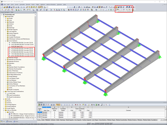
In RFEM, if you want to insert a tapered member with intermediate nodes into an existing model, the issue often arises how to determine the individual cross-section depths of the tapered members quickly. The "Connect Lines or Members" command comes in handy for this purpose.
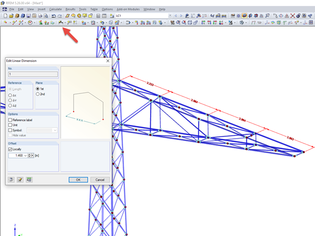
In RFEM and RSTAB, you can have contiguous dimension lines that are inclined in space.

You can use the "Free Circular Load" option in RFEM to apply a partial uplift force to a cone‑shaped floor slab. It can be defined as linearly variable. The definition of center C and the outer boundary R can be specified easily, using the select function.

In RFEM 5 and RSTAB 8, you can save problems and warnings occurring during the model check as an extra view. This way, you can easily work through the hints and messages, one after the other, cleaning the model. The function is available for double nodes, overlapping members/lines, and surfaces.
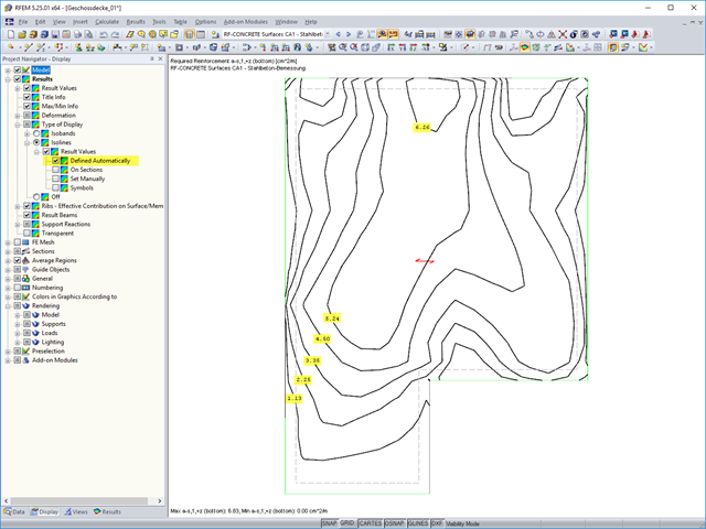
The results of an FEM calculation are usually documented by means of isobands and isolines in the graphical display of results. In the following, we will look at creating the results graphic for the black-and-white printout.

When calculating foundations according to EC 7 or EC 2, different foundation types or sizes are usually used in one object. However, boundary conditions like the soil parameters, the materials for foundations, concrete covers, and the load combinations selected for design remain the same for all foundations, as a rule.

Supports can be copied and moved using drag & drop, even if the "Move/Copy" function is not available in the shortcut menu. This applies to all kinds of supports: nodal supports, line supports, and surface supports. These can easily be assigned to further nodes, lines, or surfaces.
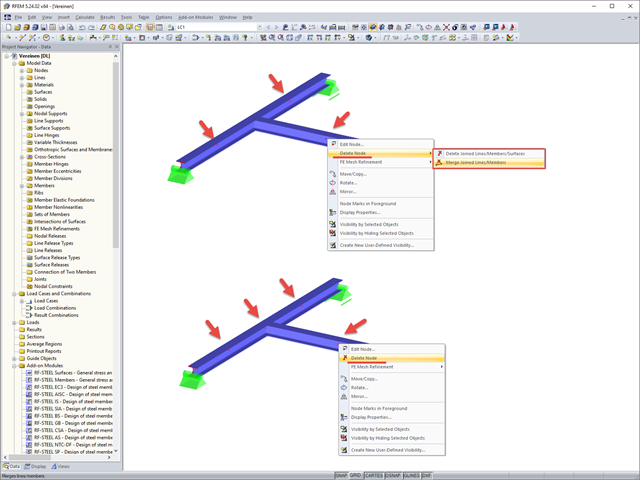
If you want to remove redundant nodes but keep connected objects, you can right-click the relevant node and select the "Delete Nodes" and "Merge Connected Members" options. In addition to members, you can also merge lines in RFEM.

In EN 1993-1-1, the General Method was introduced as a design format for stability analyses that can be applied to planar systems with arbitrary boundary conditions and variable structural height. The design checks can be performed for loading in the main load-bearing plane and simultaneous compression. The stability cases of lateral-torsional buckling and flexural buckling are analyzed from the main supporting plane; that is, about the weak component axis. Therefore, the issue often arises as to how to design, in this context, flexural buckling in the main load-bearing plane.

In RFEM, surfaces are automatically connected if they have common boundary lines. If the definition line of a surface is lying in another surface, the line is automatically integrated into the surface, provided that it is a planar surface. For quadrangle surfaces, however, automatic object detection would be relatively time-consuming. For this reason, the corresponding function is deactivated. The integrated objects must be specified manually.
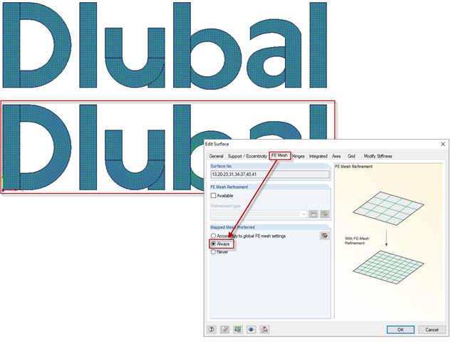
The "Mapped Mesh Preferred" option has an influence on the mesh generation of surfaces with curved and folded outlines. The program tries to align the FE mesh with the boundary lines of the surfaces.
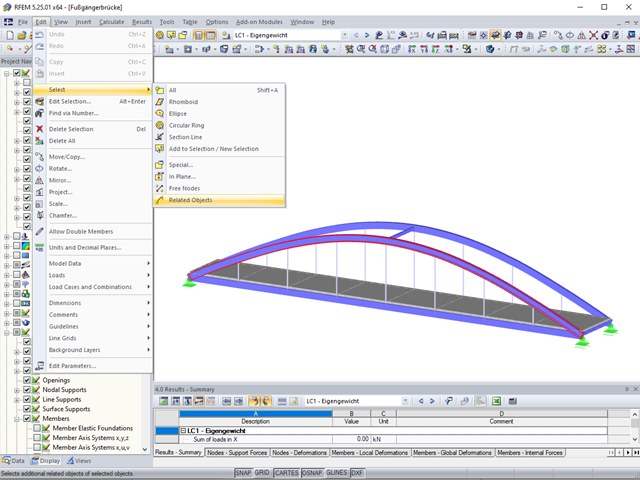
Sometimes it is necessary to add related objects, such as nodes and lines of a surface, to the selection in order to edit parts of the model.

Before creating a structural model, every user gives thought to the boundary parameters of the system and how best to represent the model. Special attention should be paid to the orientation of the global coordinate system. In engineering, the global Z‑axis is usually oriented downwards (in the direction of the dead load), while it tends to be upwards in architecture. These differences can often lead to complications during modeling; for example, when you replace global models or DXF layers.

If the geometry of a surface for which you must remove some of the existing boundary lines changes subsequently, you do not need to redefine the surface.